

Single-screw pumps, often referred to as progressive cavity pumps, are widely used for oil and lubricant transfer in industrial, marine, automotive, and process applications. This in?depth guide explains what a single-screw pump is, how it works, its advantages for handling oils and lubricants, and how to select and specify the right pump for reliable, efficient service.
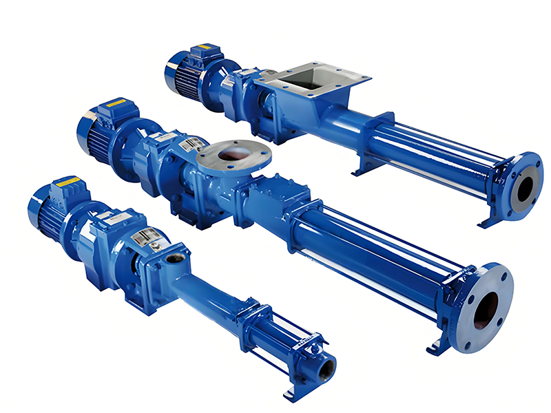
A single-screw pump is a positive displacement pump that uses a single helical rotor rotating inside an elastomer or metallic stator. As the rotor turns, it forms progressive, sealed cavities that move the fluid from the suction side to the discharge side. This design is particularly suitable for oil and lubricant transfer because it combines gentle handling, accurate flow, and strong suction capability.
In lubrication and oil transfer duties, a single-screw pump is commonly used for:
Because the flow is proportional to rotational speed and relatively insensitive to pressure fluctuations, the single-screw pump is a preferred solution when stable, metered transfer of oil and lubricant is required.
A single-screw pump is a type of positive displacement rotary pump that consists of two main elements:
As the rotor turns eccentrically inside the stator, it creates a series of sealed chambers that move axially from suction to discharge. This progressive movement of cavities gives the pump its alternative name: progressive cavity pump.
For oil and lubricant transfer, single-screw pumps are typically designed to handle a wide viscosity range, from light spindle oils to heavy gear oils. Their positive displacement nature allows them to develop high discharge pressures at relatively low speeds without excessive shear.
The working principle of a single-screw pump in oil and lubricant transfer service can be summarized in three main phases: suction, transfer, and discharge.
When the rotor begins to turn, cavities open at the suction side of the stator. These cavities expand as the rotor moves, creating a local pressure drop that draws oil or lubricant into the pump. Owing to the precise geometry between rotor and stator, leakage between cavities is minimal, so suction performance is strong even at low speeds.
As the rotor continues its eccentric rotation, the cavities filled with oil move axially along the stator. The shape and size of the cavities remain largely constant, which ensures that the volume of oil being transferred per revolution remains highly predictable. This is the basis for the pump’s volumetric accuracy.
At the discharge side, the cavities contract and expel the oil into the discharge line. Because multiple cavities are in different phases of movement at the same time, the combined output is smooth, with low pressure ripple. This low pulsation flow is beneficial for lubrication circuits, gearboxes, and hydraulic systems where stable oil supply is critical.
Using a single-screw pump for oil and lubricant transfer offers several technical and operational benefits, particularly in applications that demand reliability and accurate, low?pulsation flow.
The progressive cavity mechanism produces almost continuous flow, which is ideal for:
Single-screw pumps perform exceptionally well with viscous lubricants and high?viscosity oils. Increased viscosity typically improves volumetric efficiency rather than reducing capacity, which is often the case for centrifugal pumps. This makes them suitable for:
Due to their positive displacement design and tight internal sealing, single-screw pumps can self-prime under appropriate installation conditions. This is valuable for:
Flow rate from a single-screw pump is directly proportional to its rotational speed, largely independent of discharge pressure within design limits. This characteristic enables:
With suitable materials and clearances, a single-screw pump can handle oils containing suspended solids, wear particles, or sludge, which may be present in used lubricating oil circuits. Careful selection of rotor/stator materials and proper filtration can greatly extend service life in such conditions.
The gentle, low?shear pumping action of a single-screw pump minimizes degradation of oil additives and reduces foaming, which is beneficial for lubricant performance and life. This characteristic is important for:
Single-screw pumps are used across many industries for transferring oils and lubricants. Their combination of robust suction, viscosity tolerance, and metering accuracy makes them suitable for both transfer and dosing duties.
Selecting the correct single-screw pump for oil and lubricant transfer involves evaluating the fluid characteristics, operating conditions, and system requirements. Careful selection ensures long service life, low maintenance costs, and reliable operation.
The actual performance of a single-screw pump for oil and lubricant transfer depends on manufacturer, rotor/stator geometry, and design series. However, the following tables provide indicative ranges and commonly specified parameters that are useful for preliminary selection and comparison.
| Parameter | Indicative Range | Notes for Oil and Lubricant Applications |
|---|---|---|
| Flow Rate | 0.05 – 200 m3/h | Low?flow dosing up to medium?flow transfer systems |
| Differential Pressure | Up to 24 bar (higher with special designs) | Higher pressures possible with multi?stage geometries |
| Viscosity Range | 1 – 100,000 cSt or more | Excellent for heavy lubricants and gear oils |
| Temperature Range | -10°C to +150°C (depending on materials) | Check elastomer and seal limits for high?temperature oils |
| Solids Content | Up to 40% by volume (with optimized design) | For used oils and sludge, special materials and clearances required |
| Speed | 200 – 1500 rpm | Lower speeds recommended for high?viscosity or abrasive oils |
| Self-Priming Capability | Up to 7–8 m suction lift (theoretical) | Actual limitation depends on system NPSH and fluid properties |
| Max. Operating Pressure | Up to 25 – 48 bar (series?dependent) | Single?stage or multi?stage geometries for higher pressures |
| Component | Standard Material | Alternative Options | Selection Considerations |
|---|---|---|---|
| Rotor | Stainless Steel (e.g. 304/316) | Carbon Steel, Hardened Alloys | Use hardened grades for abrasive or contaminated oils |
| Stator | NBR (Nitrile Rubber) | FKM, EPDM, HNBR | Compatibility with synthetic oils and temperature limits is critical |
| Housing | Cast Iron | Carbon Steel, Stainless Steel | Stainless for corrosive oils or aggressive environments |
| Shaft Seals | Mechanical Seal (Carbon/Ceramic) | Cartridge Seal, Gland Packing | Pressure level, leakage tolerance, and maintenance strategy |
| O-Rings & Gaskets | NBR | FKM, PTFE | Temperature, chemical resistance, and compatibility with additives |
| Item | Specification | Comment for Oil/Lubricant Duty |
|---|---|---|
| Pump Type | Single-Screw Progressive Cavity Pump | Designed for industrial oil transfer |
| Flow Rate | 10 m3/h at 400 rpm | Proportional adjustment via speed control |
| Differential Pressure | 10 bar | Suitable for moderate-pressure lube oil circuits |
| Fluid | Mineral Lube Oil, 150 cSt at 40°C | Typical gear oil viscosity range |
| Viscosity Range | 32 – 320 cSt | Operable with standard motor and gearbox |
| Temperature | 0 – 90°C | Within standard NBR suitability |
| Rotor Material | Stainless Steel 316 | Excellent corrosion resistance in typical oil service |
| Stator Material | NBR (Oil-Resistant) | Common choice for mineral and many synthetic oils |
| Housing | Cast Iron | Robust and economical for standard oil transfer |
| Seal Type | Single Mechanical Seal | Balanced design for pressures up to 16 bar |
| Drive | Electric Motor, 4 kW, 1450 rpm with Gearbox | Speed reduction for optimal cavity filling and efficient transfer |
| Mounting | Horizontal, Baseplate Mounted | Common arrangement for pump rooms and plant rooms |
| Suction Connection | DN50 Flanged | Pipe size chosen to limit suction line velocity |
| Discharge Connection | DN40 Flanged | Allows slightly higher discharge velocity |
Proper installation of a single-screw pump is essential to ensure efficient oil and lubricant transfer, minimize wear, and extend equipment life. The following guidelines are general best practices applicable to most installations.
Once installed, following good operating practices will help maintain reliability and efficiency of single-screw pumps in oil and lubricant applications.
Routine maintenance is essential to maintain efficiency and prevent failures in single-screw oil transfer pumps. Because oils and lubricants typically provide good lubrication to pump internals, many units experience long service intervals when properly maintained.
Wear in single-screw pumps used for oils and lubricants is primarily influenced by:
Mitigation strategies include filtration, correct sizing, improved controls, and appropriate material selection.
Single-screw pumps are not the only option for oil and lubricant transfer. Comparing them with other common pump technologies helps clarify their ideal use cases.
| Aspect | Single-Screw Pump | Centrifugal Pump |
|---|---|---|
| Flow Characteristics | Positive displacement, flow ~ proportional to speed | Flow strongly dependent on head and system curve |
| Pulsation | Low pulsation, smooth output | Relatively smooth, but more sensitive to cavitation |
| Viscosity Handling | Excellent for medium to very high viscosities | Performance decreases significantly at high viscosity |
| Suction Capability | Strong self?priming capability | Generally non?self?priming without special design |
| Flow Control | Simple, via speed control | Requires throttling or speed control; less linear response |
| Applications | Lubrication systems, metering, viscous oil transfer | High?flow transfer of low?viscosity oils and fuels |
| Aspect | Single-Screw Pump | Gear Pump |
|---|---|---|
| Flow Pulsation | Very low pulsation, continuous cavities | Some pulsation associated with gear teeth |
| Solids Handling | Can handle some solids with proper design | More sensitive to solids; risk of scoring and rapid wear |
| Viscosity Range | Wide range, including very high viscosities | Works well with lubricating fluids; limited by very high viscosities |
| Shear on Fluid | Low shear, gentle handling | Higher shear, may affect some lubricant additives |
| Maintenance | Stator replacement is a key maintenance task | Gear and bearing replacement due to wear |
| Best Use Cases | Contaminated oils, variable flow, metering | Clean lubricating oils, fixed flow, high pressure |
When incorporating a single-screw pump into a larger oil transfer or lubrication system, it's important to consider overall system design, not just the pump itself.
Yes. One of the strengths of a single-screw pump is its wide viscosity handling capability. With correct sizing and speed control, the same pump type can transfer light hydraulic oils and heavier gear oils, although extreme changes in viscosity may require adjustments in speed or motor power.
Yes. Many single-screw pumps are used in continuous duty lubrication systems where reliable 24/7 operation is required. Proper material selection, filtration, and adherence to recommended operating ranges are essential to minimize wear and downtime.
Dry running should be avoided because the stator and rotor rely on the pumped fluid for lubrication and cooling. Prolonged dry running can lead to rapid stator damage, overheating, and seal failure. Protection strategies include level switches, thermal sensors, and motor power monitoring.
Maintenance intervals depend on fluid quality, operating conditions, and design. In clean oil service, stators can often operate for several thousand hours before significant wear occurs. Systems handling contaminated or abrasive oils may require more frequent inspection and replacement.
Yes. Because flow is proportional to speed and largely independent of pressure, a single-screw pump can serve as both a transfer pump and a metering pump. Integrated speed control and flow measurement allow accurate dosing of lubricants into machinery and process lines.
A single-screw pump for oil and lubricant transfer combines the strengths of positive displacement technology with smooth, low?pulsation flow, excellent viscosity handling, and strong suction performance. These characteristics make it a highly effective choice for lubrication systems, bulk oil handling, tank transfer, metering, and contaminated oil service in a wide range of industries.
When specifying or selecting a single-screw pump for oil and lubricant applications, engineers should evaluate fluid properties, system pressures, suction conditions, materials of construction, and overall system integration requirements. With proper selection, installation, and maintenance, single-screw pumps provide long?term reliability, energy?efficient operation, and precise control in demanding oil transfer and lubrication duties.
```

Copyright ? Jiangsu Longjie Pump Manufacturing Co., Ltd.


 Phone
Phone
Comment
(0)